
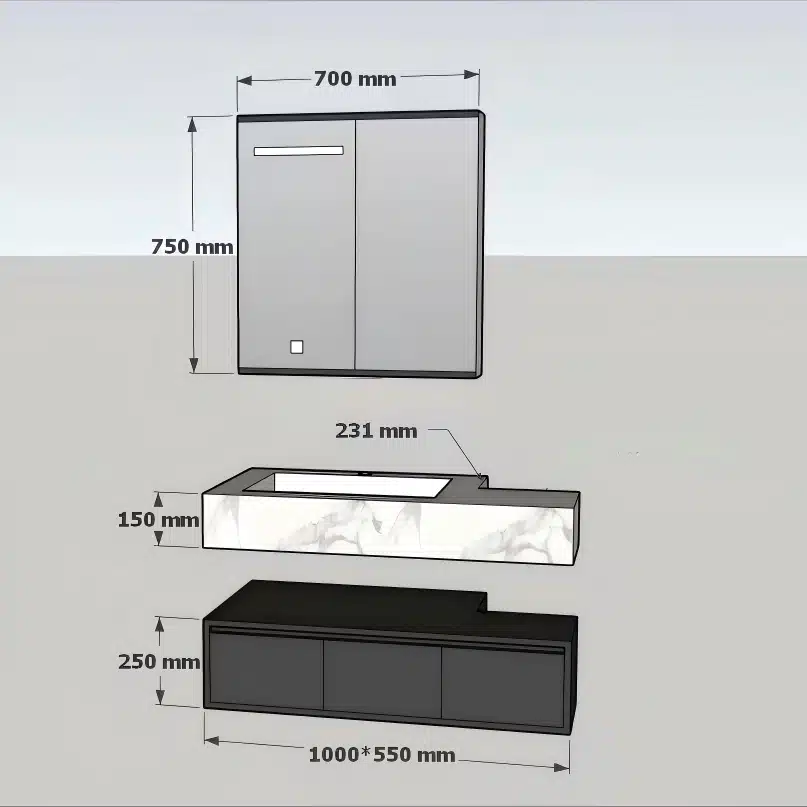
 Inefficient CAD/3D bathroom vanity design is the single biggest cause of production stalls, forcing weeks of delays that jeopardize retail timelines and supplier relationships. The approval process often gets stuck in a loop of vague feedback on sketches and conflicting emails. This communication gap between your vision and the factory’s technical team creates significant risk, leading to manufacturing errors, wasted materials, and prototypes that fail to meet specifications.
This guide provides a standard operating procedure for streamlining your design-to-production workflow. We will break down the entire process, from converting a simple sketch into a precise SolidWorks model to leveraging 3D renders for e-commerce pre-sales. We’ll also cover critical technical details, including the functional differences between DWG, STEP, and OBJ files and the essential role of exploded views in clear assembly instructions. The goal is to establish a clear, fast, and accurate system for design validation.
The “Visualization” Bottleneck: Why Is It Slowing Down Your Production?
The gap between specialized engineering CAD files and the accessible, lightweight formats needed by production, purchasing, and management teams is the primary source of visualization-related delays.
Your production timeline doesn’t slow down because of design complexity itself, but because of the friction in sharing those designs. The core problem is a technical one: translating massive, data-rich CAD files into something usable for manufacturing simulations, supplier quotes, or project management reviews. This conversion step is where inefficiencies compound and deadlines slip.
Complex Data Conversion for Collaboration
A major slowdown occurs when converting complex CAD data into formats suitable for real-time collaboration and manufacturing simulations. The translation process isn’t just a “save as” function; it’s a technical hurdle that frequently requires manual intervention and validation, directly delaying project timelines.
- Specialized engineering software is needed to prepare files for other departments. This creates a dependency on the design team, preventing other departments from working in parallel.
- Improper conversion leads to data loss or geometric inaccuracies. This forces designers to repeat work, re-validate files, and burn valuable engineering hours on administrative tasks.
Lack of Accessibility for Non-Engineering Teams
Production workflows stall when teams in purchasing, project management, and manufacturing cannot easily access or interact with 3D models. This information silo prevents quick decision-making and hides potential problems until they are expensive to fix. Keeping 3D assets locked within the engineering department is a direct barrier to operational efficiency.
- When non-engineers can’t view the models, they can’t identify procurement conflicts, assembly issues, or logistical challenges early in the process.
- Making 3D assets accessible to all stakeholders provides cross-functional visibility, which allows teams to catch design flaws before they ever reach the factory floor.
Infrastructure Strain from High-Fidelity Assets
As 3D models become more detailed for accurate simulation and photorealistic rendering, they place an enormous load on company infrastructure. Large file sizes slow down everything from network transfers and data sharing to the performance of local workstations, creating a drag on productivity across the board.
- High-fidelity models are essential for precise validation but can easily overwhelm standard hardware, leading to lag and crashes.
- Companies are now adopting optimized conversion utilities and immersive technologies like XR to accelerate design validation without bogging down internal systems.
Our CAD Service: Is a 24-Hour Turnaround Possible?
A 24-hour CAD turnaround is realistic for simple, well-defined tasks like 2D drafting or minor revisions, but complex 3D modeling requires longer timelines to ensure engineering accuracy.
What Types of Projects Can Be Completed in 24 Hours?
Yes, a 24-hour turnaround is achievable for specific, well-defined tasks. We use global teams and automation-assisted workflows to accelerate delivery for simpler projects. This makes it possible to meet urgent deadlines without sacrificing precision, especially when the project scope is clear from the start.
- Simple 2D drafting and shop drawings with clear specifications.
- PDF-to-CAD conversions for existing plans.
- Emergency revisions or minor modifications to existing design files.
When to Expect Longer Timelines for Complex Models
The complexity of the design directly impacts the delivery schedule. While we prioritize speed, intricate models require more time to ensure engineering accuracy and adherence to manufacturing standards. Rushing a complex 3D assembly introduces risks that are not worth the time saved.
- Multi-part 3D modeling and small assemblies typically require 3 to 5 business days.
- Complex mechanical designs or detailed BIM models can extend to 7 to 10 days.
- Project timelines depend on clear scope definition, high-quality source files, and prompt communication from your team.
Custom Bathroom Cabinets for Your Market

From Sketch to SolidWorks: How Does the Design Process Work?
Our process collapses the traditional design timeline by integrating parametric modeling and manufacturing constraints directly into a unified digital workflow, moving from concept to factory-ready files efficiently.
Initial Design and Parametric Modeling
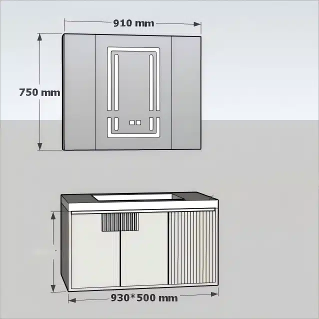
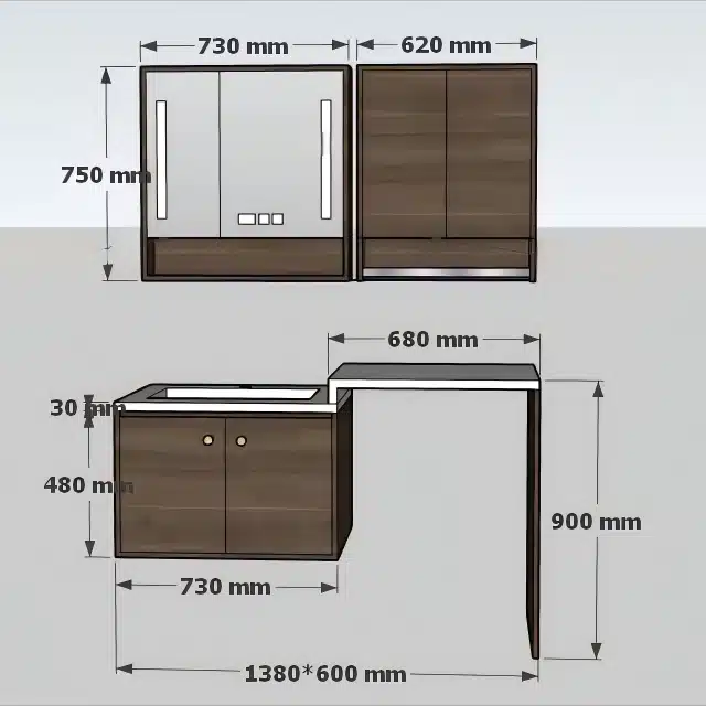
The process begins by translating initial client sketches or concepts into a flexible digital framework. We use parametric and multi-body modeling in SolidWorks to create a scalable design system, not just a static 3D object. In this system, dimensions are linked by logical relationships, so a change to one component—like cabinet width or drawer height—intelligently adjusts all connected parts. This foundational model is built to support complex and modular product lines, dramatically reducing iteration time for custom orders.
Integrating Design-for-Manufacturing (DFM)
Once the initial model is established, we integrate design-for-manufacturing (DFM) principles directly within the CAD environment. This step ensures the digital design is practical, efficient, and cost-effective to produce with our factory’s machinery and materials. We use specialized tools to check for manufacturing constraints, such as toolpath access for CNC machining or material thickness limitations for PVC or plywood. This alignment between the digital file and the physical production line prevents costly errors and delays when the order hits the factory floor.
| Process Stage | Traditional Design Workflow (Siloed) | FocusCabinet Unified Workflow (DFM-Integrated) |
|---|---|---|
| Initial Design | Static 3D models where changes require manual rework of every related part. High risk of version control errors. | Parametric 3D model. A single dimension change automatically updates the entire assembly, ensuring consistency. |
| Manufacturing Review | Design is passed to a separate production team. Issues found here force expensive redesigns and project delays. | DFM checks run continuously within SolidWorks. The design is optimized for real-world CNC machining from the start. |
| Final Output | Separate, often conflicting, files for visualization, technical drawings, and machine programming. | A single, reliable package containing all production-ready files for both visualization and factory floor fabrication. |
Developing a Unified Digital Workflow
The final stage consolidates all design elements into a single, reliable source of information. This unified digital workflow combines the 3D visualization model, the parametric constraints, and the manufacturing data into one complete package. We generate a full set of production-ready specifications and files that can be used for everything from creating photorealistic e-commerce images to programming the CNC machines. This integrated approach enables our clients, even those with small teams, to develop and order professional, factory-ready designs with confidence.
3D Rendering: How Can It Drive E-commerce Pre-Sales?
Using 3D renders for pre-sale campaigns allows e-commerce brands to validate market demand, secure revenue, and minimize financial risk before the first physical product is ever manufactured.
The traditional product development cycle relies on expensive and slow physical prototypes for marketing and sales validation. This model creates a significant lag between design finalization and market launch. 3D rendering disrupts this by enabling the creation of digital prototypes that are indistinguishable from real photos, allowing brands to launch marketing campaigns and gather feedback before committing to a full production run.
Accelerating Timelines and Reducing Prototype Costs
By replacing physical samples with digital assets, you can bypass the time and expense of manufacturing, shipping, and professionally photographing multiple versions of a product. This digital-first approach compresses the entire design-to-market timeline, as marketing materials can be developed in parallel with production planning, not after. It directly reduces the cash tied up in pre-production inventory and logistics.
- Create marketing materials and campaign assets before the first physical product is made.
- Eliminate the costs associated with shipping and photographing multiple physical prototypes.
- Compress the design-to-market cycle by gathering faster feedback on digital models.
Building Customer Confidence with Photorealistic Visuals
High-quality 3D renders bridge the trust gap in online shopping. When customers can see precise material textures, accurate scale, and realistic lighting, their purchase confidence increases. Photorealism removes the guesswork, giving buyers a clear understanding of the product they will receive. This detailed visualization directly translates to higher conversion rates, as it effectively replicates the in-store experience of examining a product up close.
- Showcase products from any angle with interactive 360-degree views.
- Allow customers to visualize different colors, materials, and custom configurations in real-time.
- Reduce return rates by setting accurate product expectations before the customer makes a purchase.
Testing Market Demand Before Committing to Inventory
Launching a new product line involves significant financial risk based on market forecasts. 3D renders allow you to replace forecasting with real-world data. By creating pre-order pages and ad campaigns using only digital visuals, you can gauge customer interest and collect sales before placing a large manufacturing order. This data-driven strategy ensures you only produce what the market has already validated, minimizing the risk of overproduction and unsold inventory.
- Launch pre-order pages using only digital assets to validate demand for new designs.
- Use A/B testing with different rendered visuals to identify which features or colors perform best.
- Adjust initial production volume based on actual pre-sale data instead of market forecasts.
Exploded Views: Why Are They Essential for Assembly Instructions?
Exploded view diagrams are a non-negotiable tool for any manufacturer, directly reducing assembly errors, support costs, and internal training time.
Minimizing Assembly Errors for End-Users
Exploded views function as a clear visual map, showing exactly how individual components connect and relate to one another. This clarity eliminates the guesswork and ambiguity common in text-only manuals, which prevents incorrect assembly. Getting it right the first time reduces customer frustration, minimizes support calls, and protects your brand’s reputation.
- Visual breakdowns show exactly how parts fit, leaving little room for interpretation errors.
- Clear part identification helps users quickly locate and orient components correctly.
- Effective instructions directly lower product returns and damage caused by improper assembly.
Improving Manufacturing and Training Efficiency
The value of exploded views extends far beyond the customer. On the factory floor, they are a vital tool for training new assembly line staff, establishing a universal guide that standardizes the process and speeds up onboarding. Engineers also use these visuals to optimize packaging. By understanding how components fit together, they can design safer, more logical packaging solutions—like our “E-commerce Ready” ISTA 3A certified cartons—that protect parts and lower logistics costs.
- Acts as a primary training resource for production teams to standardize assembly workflows.
- Aids in creating efficient packaging plans that reduce material waste and protect parts in transit.
- Provides a quick reference for quality control teams to verify correct component placement.
File Formats: How Do DWG, STEP, and OBJ Differ?
Choosing the right file format isn’t a technicality; it’s a critical decision that dictates whether a design is suitable for manufacturing, visualization, or architectural planning.
Different project stages require different types of data. Sending a manufacturer a file meant for 3D rendering will cause production errors, while sending a simple 2D blueprint to a marketing team is useless for creating e-commerce assets. Understanding the core function of each format prevents costly communication breakdowns and ensures data integrity from one department to the next.
| File Format | Primary Use Case | Key Characteristics |
|---|---|---|
| STEP (.stp, .step) | 3D Manufacturing & Engineering | ISO standard; preserves complex surface data for CAM/CNC. |
| OBJ (.obj) | 3D Graphics & Visualization | Stores surface geometry and texture data; widely supported. |
| DWG (.dwg) | 2D/3D Technical Drafting | Proprietary AutoCAD format; supports layers for architectural plans. |
STEP (.stp, .step): The Standard for Manufacturing
STEP is the international standard (ISO 10303) for exchanging 3D CAD data between different software systems. Its purpose is to preserve complex geometric accuracy, making it the definitive format for engineering and manufacturing. When a design needs to move from a designer’s software to a factory’s CAM system, STEP is the file type that ensures nothing gets lost in translation.
- Functions as a neutral format, ensuring interoperability across various CAD platforms.
- Accurately captures complex designs, including curved surfaces and product assemblies.
- Used to send precise models to manufacturers without losing critical design data.
OBJ (.obj): The Choice for 3D Graphics and Printing
The OBJ format is a simple, text-based file type used widely in 3D graphics, animation, and 3D printing. It efficiently stores 3D geometry—the shape of an object—and works with an MTL file to define colors, textures, and materials. It’s built for visual representation, not mechanical precision, making it perfect for creating photorealistic renders or a quick prototype on a 3D printer.
- Ideal for applications that require visual representation, like rapid prototyping and digital rendering.
- Stores surface geometry along with texture maps and color information via an accompanying .mtl file.
- Supported by nearly all 3D graphics software, making it highly portable for visualization tasks.
DWG (.dwg): The Foundation for 2D and 3D Drafting
DWG is a proprietary file format native to AutoCAD, which has made it the industry staple for architectural and engineering drawings for decades. It is primarily used for creating precise 2D blueprints and technical 3D models. When an architect or contractor needs detailed construction schematics with exact dimensions and layers, DWG is the standard format they rely on.
- Serves as the standard format in architecture, engineering, and construction for technical plans.
- Supports both 2D layers and 3D solid objects within a single file.
- Used for creating detailed blueprints, construction schematics, and mechanical diagrams.
Design File Ownership: Who Retains the Intellectual Property?
By default, the designer who creates the CAD files owns the intellectual property, but this ownership is frequently altered by employment status or explicit contractual agreements.
Default Ownership: The Creator’s Rights
The default legal position is that the designer, architect, or engineer who creates design files is the automatic owner of the copyright. This ownership is established the moment the work is created, granting the creator exclusive rights without any need for formal registration. Under U.S. Copyright Law, these plans, drawings, and CAD files are considered “Instruments of Service,” and their creator is legally deemed the author. This means freelancers and independent contractors retain full copyright unless they explicitly transfer these rights through a signed, written agreement.
The ‘Work-for-Hire’ Doctrine for Employees
The main exception to the creator-ownership rule is the ‘work made for hire’ doctrine. If a designer creates work as a direct employee and the work falls within their regular job scope, the employer is legally considered the author and owner of the design. This doctrine automatically assigns the copyright to the employer for any work an employee produces as part of their duties. The company then holds all exclusive rights to reproduce, distribute, display, and create derivative works from those design files.
Contractual Agreements: Transferring or Licensing Rights
Written contracts are the most effective tool for clarifying intellectual property rights and can override any default ownership rules. These agreements prevent costly legal disputes by defining exactly who owns the final files and how they can be used. Service agreements should explicitly state whether ownership is fully transferred to the client or if the client is simply granted a license for specific uses. Without a clear contract, a client’s use of design files after a project concludes or a designer is terminated can easily lead to copyright infringement claims.
Conclusion
A streamlined visualization process is essential for reducing production lead times and ensuring design accuracy. Our CAD and rendering services translate your concepts—from a simple sketch to detailed specifications—into precise, manufacturable plans. This clarity helps you secure approvals, generate pre-sales, and confidently move into production.
Send us your sketch or project requirements to see our design process in action. Our team is ready to deliver a detailed CAD model and render to help accelerate your next product launch.
Frequently Asked Questions
Do factories offer free vanity design?
Most factories offer complimentary design assistance for standard modifications and bulk orders, as it’s part of their B2B service. For fully bespoke, from-scratch designs, a design fee is common but is often credited back to the project upon final purchase, effectively making it free for serious buyers.
How to get 3D renders of bathroom vanities?
You can obtain 3D renders by providing your design specifications or CAD files to the manufacturer. Their internal design team or a partner visualization studio will then use this data to create photorealistic images. The process involves applying accurate materials, setting up professional lighting, and rendering the scene, which converts the technical 3D model into a high-fidelity marketing asset.
Best software for vanity design?
The best software depends on the task. For precise engineering and manufacturing, industry standards are SolidWorks, AutoCAD, and Fusion 360. For conceptual design and high-quality visualization, teams use Blender, 3ds Max, and V-Ray. For integrating the vanity into a full room layout, interior design platforms like Chief Architect and 2020 Design Live are preferred.
Can I get CAD drawings for my architect?
Yes, absolutely. Providing CAD drawings (typically in .DWG, .DXF, or .STEP formats) to your architect is a standard and critical step. These technical files ensure that the vanity’s dimensions, plumbing connections, and electrical requirements are accurately integrated into the architectural plans, preventing conflicts during construction. This cross-functional sharing of design data is essential for modern project management.
How to visualize custom vanity?
The visualization process typically starts with your ideas or sketches, which are turned into a detailed 3D model. From there, you can receive photorealistic 3D renders showing the vanity from multiple angles with your chosen materials and finishes. For a more interactive experience, many firms now offer real-time 3D viewers or use Augmented Reality (AR) to project a virtual model of the vanity into your actual space using a smartphone or XR headset.
Cost of 3D product rendering?
The cost of 3D product rendering varies based on complexity and context. A basic studio render against a simple background can range from $200 to $500. For a more detailed “lifestyle” render that places the vanity in a fully furnished bathroom scene, costs typically range from $600 to over $2,500. Factors influencing price include model complexity, material detail, and the number of unique camera angles required.



0 Comments